What is Rogers TMM PCB?
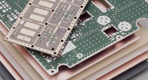
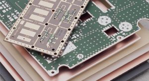
Rogers TMM PCB Manufacturer,Rogers TMM PCB is a high-frequency laminate material renowned for its exceptional electrical performance in RF and microwave applications. With a low dielectric constant and loss tangent, it ensures minimal signal loss and high-speed transmission. This substrate offers excellent dimensional stability and thermal conductivity, making it ideal for demanding environments. Rogers TMM PCB is widely used in aerospace, defense, and telecommunications industries, where reliability and performance are crucial. Its advanced material composition and precise manufacturing processes enable the development of compact, high-density electronic assemblies with superior signal integrity and thermal management capabilities.
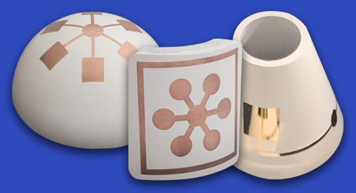
TMM high frequency laminates are ideal for high reliability strip-line and micro-strip applications due to their electrical and mechanical stability. All dielectric variants can be produced as molded, 3-dimensional shapes. Shaped TMM components open up a new range of innovative design solutions for high or low frequency applications requiring controlled dielectric constant with low loss.
Benefits
- Wide range of dielectric constants (Dks)
- Excellent mechanical properties, resists creep and cold flow
- Exceptionally low thermal coefficient of Dk
- Coefficient of thermal expansion matched to copper allowing for high reliability of plated through-holes
- Available copper clad in larger formats, allowing the use of standard PCB subtractive processes
- Resistant to process chemicals, no damage to material during fabrication and assembly processes
- Thermoset resin for reliable wire bonding
- No specialized production techniques required
- TMM 10 and 10i laminates can replace alumina substrates
- RoHS compliant, environment friendly
- Third party metallization available
Rogers TMM PCB is a type of printed circuit board (PCB) crafted from Rogers Corporation’s TMM material, which blends Teflon™ with Microstrip technology. Rogers Corporation is renowned for manufacturing high-performance materials, and TMM, a composite material, is widely utilized in the production of high-frequency and microwave circuits. This PCB variant is commonly applied in scenarios demanding top-notch performance and accurate signal transmission, including radio frequency (RF) and microwave circuits.
TMM PCB utilizes the excellent electrical properties of Teflon™ material, combined with microstrip line technology, to provide low loss, high-frequency, and stable signal transmission capabilities. This type of PCB finds widespread use in areas such as communications, radar, satellite communication, where precise control of signals and minimal signal loss are crucial.
In summary, Rogers TMM PCB is a high-performance printed circuit board designed for high-frequency and microwave applications. Through the use of special materials and processes, it ensures high-quality signal transmission.
Rogers TMM PCB Manufacturer
How Does Rogers TMM PCB Function?
The function of Rogers TMM PCB depends on its materials and structural design. Here are the main features and working principles of Rogers TMM PCB:
Superior Electrical Characteristics: TMM PCB utilizes Teflon™ and microstrip line technology, providing excellent electrical characteristics, including low loss, high dielectric constant, and high-frequency performance. These attributes make it excel in high-frequency and microwave applications.
Low Loss: Teflon™ material is known for its low loss and low dielectric loss characteristics, helping to reduce energy loss during signal transmission, thereby improving the efficiency of the circuit.
Precise Signal Transmission: The design and material selection of TMM PCB aim to ensure precise signal transmission. It offers stable signal transmission in high-frequency environments, suitable for applications that demand precision control and reliability, such as radio frequency and microwave communication.
High-Frequency Applications: Due to its special material composition and structural design, Rogers TMM PCB is particularly suitable for high-frequency applications. This includes wireless communication, radar, satellite communication, and other fields that require signal stability and accuracy in the high-frequency range.
In summary, the functionality of Rogers TMM PCB is primarily manifested in its superior electrical characteristics, low loss, precise signal transmission, and capability for high-frequency applications. This makes it an ideal choice for many high-performance electronic devices.
| ELECTRICAL PROPERTIES⁽¹⁾ | TYPICAL VALUES | DIRECTION | UNITS | CONDITIONS | TEST METHOD | ||||||
| TMM3 | TMM4 | TMM6 | TMM10 | TMM10i | TMM13i | ||||||
| Dielectric Constant (process) | 3.27 ±
0.032 |
4.50 ±
0.045 |
6.00 ±
0.080 |
9.20 ±
0.230 |
9.80 ±
0.245 |
12.85 ±
0.35 |
Z | _ | 10 GHz | IPC-TM-650
method 2.5.5.5 |
|
| Dielectric Constant (design) | 3.45 | 4.7 | 6.3 | 9.8 | 9.9 | 12.2 | _ | _ | 8 GHz – 40 GHz | Differential Phase Length
Method |
|
| Dissipation Factor (process) | 0.002 | 0.002 | 0.0023 | 0.0022 | 0.0019 | 0.0019 | Z | _ | 10 GHz | IPC-TM-650 method
2.5.5.5 |
|
| Thermal Coefficient of Dielectric
Constant |
37 | 15 | -11 | -38 | ’-43﹡ | -70 | _ | ppm/°K | ,-55 to +125°C | IPC-TM-650 method
2.5.5.5 |
|
| Insulation Resistance | >2000 | >2000 | >2000 | >2000 | >2000 | >2000 | _ | Gohm | C/96/60/95 | ASTM D257 | |
| Volume Resistivity | 3X10⁹ | 6X10⁸ | 1X10⁸ | 2X10⁸ | 2X10⁸ | _ | _ | Mohm
cm |
_ | ASTM D257 | |
| Surface Resistivity | >9X10⁹ | 1X10⁹ | 1X10⁹ | 4X10⁷ | 4X10⁷ | _ | _ | Mohm | _ | ASTM D257 | |
| Electrical Strength (dielectric
strength) |
441 | 371 | 362 | 285 | 267 | 213 | Z | V/mil | _ | IPC-TM-650 method
2.5.6.2 |
|
| Thermal Properties⁽¹⁾ | |||||||||||
| Decomposition Temperature (Td) | 425 | 425 | 425 | 425 | 425 | 425 | 425 | °C TGA | _ | ASTM D3850 | |
| Coefficient of Thermal Expansion – x | 15 | 16 | 18 | 21 | 19 | 19 | X | ppm/K | 0 to 140°C | ASTM E 831
IPC-TM-650, 2.4.41 |
|
| Coefficient of Thermal Expansion – y | 15 | 16 | 18 | 21 | 19 | 19 | Y | ppm/K | 0 to 140°C | ASTM E 831 IPC-TM-650, 2.4.41 | |
| Coefficient of Thermal Expansion – z | 23 | 21 | 26 | 20 | 20 | 20 | Z | ppm/K | 0 to 140°C | ASTM E 831
IPC-TM-650, 2.4.41 |
|
| Thermal Conductivity | 0.7 | 0.7 | 0.72 | 0.76 | 0.76 | _ | Z | W/m/K | 80°C | ASTM C518 | |
| Mechanical Properties⁽¹⁾ | |||||||||||
| Copper Peel Strength after Thermal
Stress |
5.7
(1.0) |
5.7
(1.0) |
5.7
(1.0) |
5.0
(0.9) |
5.0
(0.9) |
4.0
(0.7) |
X,Y | lb/inch
(N/mm) |
after solder
float 1 oz. EDC |
IPC-TM-650
Method 2.4.8 |
|
| Flexural Strength (MD/CMD) | 16.53 | 15.91 | 15.02 | 13.62 | _ | _ | X,Y | kpsi | A | ASTM D790 | |
| Flexural Modulus (MD/CMD) | 1.72 | 1.76 | 1.75 | 1.79 | ‘1.80﹡ | _ | X,Y | Mpsi | A | ASTM D790 | |
| Physical Properties⁽¹⁾ | |||||||||||
| Moisture
Absorption (2X2) |
1.27mm (0.050”) | 0.06 | 0.07 | 0.06 | 0.09 | 0.16 | 0.16 | _ | % | D/24/23 | ASTM D570 |
| 3.18mm (0.125”) | 0.12 | 0.18 | 0.2 | 0.2 | 0.13 | 0.13 | |||||
| Specific Gravity | 1.78 | 2.07 | 2.37 | 2.77 | 2.77 | 3 | _ | _ | A | ASTM D792 | |
| Specific Heat Capacity | 0.87 | 0.83 | 0.78 | 0.74 | ,0.72﹡ | _ | _ | J/g/K | A | Calculated | |
| Lead-Free Process Compatible | YES | YES | YES | YES | YES | YES | _ | _ | _ | _ | |
What Types of Package Substrate and Chip Package Technology Include Rogers TMM PCB?
Rogers TMM PCB is typically used in conjunction with high-performance chip packaging technologies and substrate materials. Here are some packaging substrates and chip packaging technologies that may be associated with Rogers TMM PCB:
Packaging Substrates:
High-Frequency Radio Frequency (RF) Packaging Substrates: The superior electrical properties of Rogers TMM PCB make it an ideal choice for high-frequency RF packaging. This type of substrate is commonly used in RF front-end modules, communication devices, and radar systems.
Microwave Packaging Substrates: Due to its excellent performance in the microwave frequency range, Rogers TMM PCB is suitable for microwave packaging, such as microwave integrated circuits used in high-frequency communication and sensor applications.
Chip Packaging Technologies:
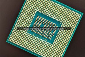
Ball Grid Array (BGA) Packaging: BGA packaging is a common chip packaging technology suitable for high-density integrated circuits. Rogers TMM PCB may be used to support BGA packaging that requires high-frequency transmission and stable signal performance.
RF Packaging: Thanks to the outstanding performance of TMM PCB, it might be chosen for the packaging of RF chips to ensure high-quality signal transmission and interface connectivity.
In summary, Rogers TMM PCB is often associated with high-frequency RF and microwave packaging substrates, as well as some common chip packaging technologies, to meet the stringent requirements of applications that demand high electrical performance and signal transmission quality.
How Does Rogers TMM PCB Differ from Traditional PCBs?
Rogers TMM PCB differs from traditional PCBs primarily in terms of materials, electrical performance, and application areas:
Materials: Rogers TMM PCB uses Rogers Corporation’s proprietary TMM material, which includes Teflon™ and Microstrip technology. In contrast, traditional PCBs typically use common materials such as glass fiber-reinforced epoxy resin (FR-4).
Electrical Performance: Rogers TMM PCB is designed for high-frequency and microwave applications, featuring superior electrical properties such as low loss, high dielectric constant, and high-frequency performance. Traditional PCBs may not excel in these aspects as much as materials specifically designed for high-frequency applications.
Application Areas: Rogers TMM PCB is commonly used in fields that demand high precision and stability in signal transmission, such as RF and microwave communication, radar, and satellite communication. Traditional PCBs find broader applications in general electronic devices, including computers, consumer electronics, and industrial control.
Cost: Due to the use of specialized high-performance materials, Rogers TMM PCB is typically relatively expensive, while traditional PCBs use common materials, offering a more cost-effective solution.
Manufacturing Process: As Rogers TMM PCB is designed for specific applications, its manufacturing process may require higher technical expertise and precision compared to the manufacturing process of traditional PCBs.
In summary, Rogers TMM PCB focuses more on high performance and specialized requirements in terms of material selection, electrical performance, and applications, whereas traditional PCBs are more suitable for general-purpose electronic devices. The choice between the two types of PCB depends on the specific requirements of the application and budget considerations.
What Constitutes the Main Structure and Production Technologies of Rogers TMM PCB?
The main structure and production technologies of Rogers TMM PCB include the following aspects:
Substrate Material: The substrate of Rogers TMM PCB is made from Rogers Corporation’s proprietary TMM (Teflon™/Microstrip/Microstrip) material. This material is a composite that combines Teflon™ and Microstrip technology to provide excellent electrical performance.
Microstrip Line Technology: Microstrip line technology is a crucial component of Rogers TMM PCB, used to facilitate the transmission of high-frequency and microwave signals. Microstrip lines typically consist of a metal conductor (usually copper) deposited on the surface of the substrate, controlling the signal through their specific design and width.
Layered Structure: Rogers TMM PCB usually adopts a multilayer structure, with different layers serving as signal layers, ground layers, power layers, etc., to accommodate complex circuit designs. A multilayer structure helps reduce electromagnetic interference, improving performance and reliability.
Impedance Control: Due to the high requirements for signal impedance control in high-frequency applications, the production technology of Rogers TMM PCB often includes precise impedance control. This is achieved by controlling the width, spacing, and substrate material properties of the microstrip lines.
Special Processes: As Rogers TMM PCB is typically used in high-performance and high-frequency applications, the production process may involve special techniques such as precision chemical etching, metallization, and the fabrication of fine circuits.
In summary, the main structure of Rogers TMM PCB includes special TMM material, microstrip line technology, a multilayer structure, and impedance control. The production technologies encompass specialized processes to ensure high performance and precise signal transmission.
| Standard Thicknesses | Standard Panel Sizes | Standard Claddings | |||||
| 0.015” (0.381mm) +/- 0.0015”
0.025” (0.635mm) +/- 0.0015” 0.030” (0.762mm) +/- 0.0015” 0.050” (1.270mm) +/- 0.0015” 0.060” (1.524mm) +/- 0.0015” 0.075” (1.900mm) +/- 0.0015” |
0.100” (2.500mm) +/- 0.0015”
0.125” (3.175mm) +/- 0.0015” 0.150” (3.810mm) +/- 0.0015” 0.200” (5.080mm) +/- 0.0015” 0.250” (6.350mm) +/- 0.0015” 0.500” (12.70mm) +/- 0.0015” |
18” X 12” (457mm X 305mm)
18” X 24” (457mm X 610mm) *Additional panel sizes available |
Electrodeposited Copper Foil
½ oz. (18µm) HH/HH 1 oz. (35µm) H1/H1 *Additional claddings such as heavy metal and unclad are available |
||||
What FAQs Surround Rogers TMM PCB?
What is Rogers TMM PCB?
Rogers TMM PCB is a type of printed circuit board that utilizes Rogers Corporation’s TMM material, designed specifically for high-frequency and microwave applications.
What are the characteristics of TMM material?
TMM material is a proprietary material from Rogers Corporation, comprising Teflon™ and Microstrip technology. It features low loss, high dielectric constant, and properties suitable for high-frequency applications.
What applications is Rogers TMM PCB suitable for?
Rogers TMM PCB is commonly used in fields with high-performance requirements and a need for high precision and stability in signal transmission, such as RF communication, microwave circuits, radar, and satellite communication.
How does Rogers TMM PCB differ from traditional PCBs?
Compared to traditional PCBs, Rogers TMM PCB is more focused on high performance and specialized requirements in terms of materials, electrical performance, and applications. It is typically used for specific high-frequency and microwave applications.
What is the manufacturing process of Rogers TMM PCB?
The manufacturing of Rogers TMM PCB involves special processes, including the use of TMM material, microstrip line technology, multilayer structure design, impedance control, etc., to ensure high performance and precise signal transmission.
What is the cost of TMM PCB?
Due to the use of high-performance materials, Rogers TMM PCB is typically relatively expensive, with costs slightly higher than traditional PCBs.
Why is Rogers TMM PCB Crucial for the Future of PCB Engineering?
Rogers TMM PCB is crucial for the future of PCB engineering for several reasons:
Increasing Demand for High-Frequency Applications: As communication, radio frequency (RF), and microwave technologies continue to advance, there is a growing demand for high-frequency applications. Rogers TMM PCB is favored for its excellent electrical performance in the high-frequency range, making it essential for supporting the development of future high-frequency communication and radar systems.
Development of Internet of Things (IoT) and 5G Technology: With the widespread adoption of the Internet of Things (IoT) and 5G technology, the performance requirements for PCBs become more stringent. Rogers TMM PCB can provide high-performance signal transmission, meeting the requirements for signal stability and data transfer rates imposed by these emerging technologies.
Microelectronics Packaging Demands: With the advancement of microelectronics packaging technology, the requirements for PCBs are increasing. Rogers TMM PCB excels in microwave packaging and high-density integrated circuits, providing crucial technological support for the future of microelectronics packaging.
Importance of Precision Signal Transmission: Precision signal transmission is critical in many applications, particularly in RF communication and radar systems. Rogers TMM PCB, with its superior electrical characteristics and impedance control, plays a vital role in facilitating precise signal transmission.
Future High-Speed Computing Demands: As the demand for high-speed and high-performance computing increases in computers and data centers, the need for advanced PCB technology supporting high-speed signal transmission is also growing. The advantages of Rogers TMM PCB in high-frequency and high-speed data transmission make it a key technology for the future of high-speed computing.
In summary, the outstanding performance of Rogers TMM PCB positions it as a crucial element in the future of PCB engineering, addressing the evolving demands of high-frequency, high-speed, and high-performance applications requiring precision circuit boards.
 Professional high frequency circuit board supplier
